Quadcopter PID Flight Controller & Digital Twin
Custom quadcopter flight controller with PID stabilization and digital twin visualization. Features Arduino-based attitude control, BNO055 IMU integration, and Gazebo physics simulation with hardware-in-the-loop testing capabilities.
Digital Twin Simulation
Live Gazebo visualization of quadcopter attitude driven by physical IMU sensor data via TCP/IP streaming.
Hardware Test Stand
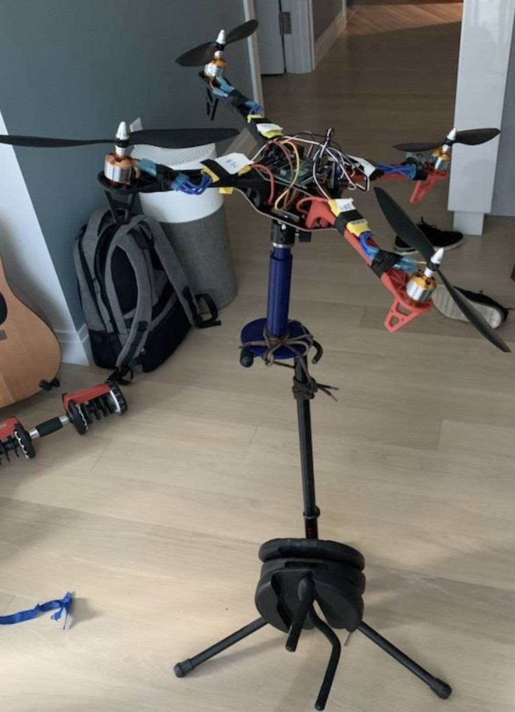
Quadcopter mounted on hardware test stand
Quadcopter is mounted on a gimble that I screwed into a 3D-printed stand (including the internal threading). I then tied that to a guitar stand weighed down with dumbbell plates.
Overview
This project implements a custom flight controller for a quadcopter platform with integrated digital twin capabilities. The system consists of two main components: an Arduino-based PID controller for attitude stabilization, and a Gazebo physics simulation that mirrors the physical hardware's orientation in real-time.
The flight controller uses an Adafruit BNO055 9-axis IMU to measure roll, pitch, and yaw angles, then applies PID control to maintain stable flight. A complementary digital twin plugin streams IMU data to Gazebo via TCP/IP sockets, enabling hardware-in-the-loop testing and visualization without risking the physical hardware.
System Architecture
Flight Controller Components
- • Arduino Microcontroller: Main processing unit running control loop at 100ms intervals
- • Adafruit BNO055 IMU: 9-axis sensor (accelerometer, gyroscope, magnetometer) with external crystal for precision
- • Brushless Motors: Four ESC-controlled motors with PWM signals (1000-1850μs)
- • Safety Timers: Automatic motor shutoff after 15 seconds of operation
Digital Twin Pipeline
- • Serial Communication: Arduino streams roll/pitch/yaw data at 19200 baud over USB
- • Middleware Bridge: C++ application reads serial data and forwards to TCP/IP socket (port 12345)
- • Gazebo Plugin: Custom ModelPlugin receives orientation data and updates simulation pose
- • Real-Time Sync: 50ms update rate maintains visual fidelity with physical hardware
Data Flow Architecture
PID Control System
Control Loop Architecture
The flight controller implements a classic PID (Proportional-Integral-Derivative) control algorithm for each axis (roll, pitch, yaw). The control loop executes at 10Hz with complementary filtering to reduce noise in the derivative term.
// Calculate error for each axis
error_current[ROLL] = orientation_current[ROLL] - orientation_setpoint[ROLL];
error_current[PITCH] = orientation_current[PITCH] - orientation_setpoint[PITCH];
error_current[YAW] = orientation_current[YAW] - orientation_setpoint[YAW];

// Proportional term
pid_p[ROLL] = gain_p[ROLL] * error_current[ROLL];

// Derivative term with complementary filter (0.9 weight)
pid_d_new[ROLL] = gain_d[ROLL] * (error_current[ROLL] - error_prev[ROLL]) / time_elapsed;
pid_d[ROLL] = filter * pid_d[ROLL] + (1 - filter) * pid_d_new[ROLL];

// Combined PID output
pid_current[ROLL] = pid_p[ROLL] + pid_i[ROLL] + pid_d[ROLL];
PID Gains
Motor Mixing Algorithm
PID outputs are combined with base thrust to generate individual motor commands:
motor1 = thrust + roll + pitch + yaw  // FR
motor2 = thrust - roll + pitch - yaw  // FL
motor3 = thrust + roll - pitch - yaw  // BR
motor4 = thrust - roll - pitch + yaw  // BL
Flight Controller Features
- Automatic IMU calibration on startup
- ESC calibration sequence for motor sync
- PWM thrust clamping (1000-1850μs range)
- Complementary filter for noise reduction
- Safety timer with automatic shutoff
- Serial debugging output for tuning
- Zero-setpoint hovering mode
- External crystal timing for precision
Digital Twin & Simulation
Gazebo Plugin Architecture
The digital twin leverages a custom Gazebo ModelPlugin that connects to the hardware bridge via TCP/IP sockets. On each simulation update cycle, the plugin receives orientation data as a comma-separated string, parses the roll/pitch/yaw values, and updates the quadcopter model's pose in the virtual environment.
class ArduinoIMU : public ModelPlugin {
    Socket::Ptr m_client = std::make_shared<Socket>("127.0.0.1", 12345);

    void OnUpdate() {
        // Receive orientation string from TCP socket
        std::string output = m_client->socket_receive();

        // Parse roll, pitch, yaw from comma-separated values
        std::stringstream ss(output);
        std::vector<std::string> v;
        while (ss.good()) {
            std::string substr;
            std::getline(ss, substr, ',');
            v.push_back(substr);
        }

        // Convert to degrees and update Gazebo model pose
        double roll_w = std::stod(v[0]) * 0.01745;  // deg to rad
        double pitch_w = std::stod(v[1]) * 0.01745;
        double yaw_w = std::stod(v[2]) * 0.01745;

        ignition::math::Pose3d pose(0.0, 0.0, 5.0, roll_w, pitch_w, yaw_w);
        this->model->SetWorldPose(pose);
    }
};
Serial-to-TCP Bridge
A multi-threaded C++ application handles the interface between Arduino serial communication and network sockets:
- • Thread 1: Reads IMU data from /dev/ttyACM1 at 19200 baud
- • Thread 2: Forwards orientation strings to TCP socket at 50ms rate
- • String Formatting: Ensures 6-character padding for consistent parsing
Build & Dependencies
Gazebo Plugin:
- • Gazebo 11+ (physics, common, headers)
- • Ignition Math library
- • Custom socket client wrapper
- • C++17 standard with -fPIC
Serial Bridge:
- • Third-party serial library
- • POSIX threads (pthreads)
- • CMake 3.5+ build system
Hardware Configuration
Sensor Setup
BNO055 IMU Connections:
- • SCL → Arduino Analog 5
- • SDA → Arduino Analog 4
- • VDD → 3.3-5V DC
- • GND → Common Ground
I2C Address: 0x28 (default)
Sample Rate: 50ms (20Hz)
Motor Layout
PWM Pin Assignments:
- • Motor 1 (FR) → Pin 13
- • Motor 2 (FL) → Pin 11
- • Motor 3 (BR) → Pin 9
- • Motor 4 (BL) → Pin 8
PWM Range: 1000-1850μs
Hover Thrust: ~1350μs
Reference Frame
BNO055 Orientation:
     +----------+
     |         *| RST
 ADR |*        *| SCL
 INT |*        *| SDA    ^      /->
 PS1 |*        *| GND    |      |
 PS0 |*        *| 3VO    Y  Z-> \-X
     |         *| VIN
     +----------+

 ROLL  → Z-axis
 PITCH → Y-axis
 YAW   → X-axis
Getting Started
1 Flight Controller Setup
Clone repository:
git clone https://github.com/aarwitz/Quadcopter-PID-Controller.git- 1. Open
FC_latest.inoin Arduino IDE - 2. Install Adafruit BNO055 and Servo libraries
- 3. Connect Arduino and upload code
- 4. Wait for automatic IMU/ESC calibration
- 5. Monitor serial output for PID tuning
2 Digital Twin Setup
Build serial bridge:
cd SerialCom/build
cmake -S ../src -B .
make -j$(nproc)
sudo chmod a+rw /dev/ttyACM1
./ArduinoSerial
Build Gazebo plugin:
cd Gazebo_Plugin/build
cmake -S ../ -B .
make -j$(nproc)
export GAZEBO_PLUGIN_PATH=$GAZEBO_PLUGIN_PATH:$PWD
gzserver -u Quad.world
Technical Highlights
Control Theory
- Independent 3-axis PID control for roll, pitch, yaw stabilization
- Complementary filter reduces high-frequency noise in derivative term
- Motor mixing algorithm distributes control effort across four motors
- PWM saturation limits prevent motor over-speed or stall conditions
Software Engineering
- Multi-threaded C++ architecture for concurrent serial/socket I/O
- Custom Gazebo ModelPlugin integrates with simulation event loop
- TCP/IP socket abstraction provides clean hardware-software interface
- CMake build system with dependency management for cross-platform builds
Future Enhancements
- → Implement altitude hold using barometric pressure sensor
- → Add GPS waypoint navigation for autonomous flight
- → Integrate optical flow for velocity estimation
- → Implement emergency failsafe modes (e.g., return-to-home)
- → Develop web-based ground control station for tuning
- → Add RC receiver input for manual override
- → Implement state estimation using Extended Kalman Filter
- → Enable bidirectional digital twin for simulation-based testing